It is time to Work with a real device
Fact
Exactly the same code you wrote in the simulator, works on the real device, but in the real device you can do even more!
- You can easily download the code from Wokwi in the form of a zip project file.

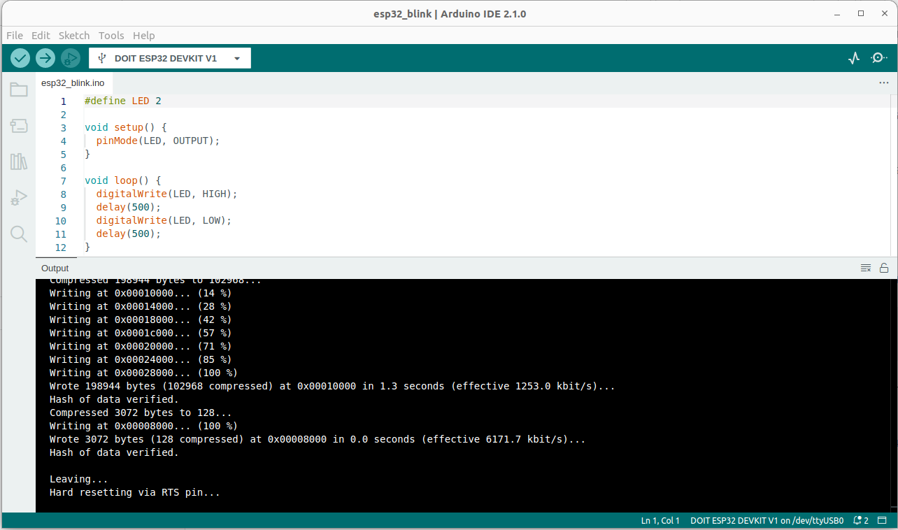
- One convenient possibility is to use Arduino IDE
- Since we are using the ESP32, you have to follow these intructions
- Select the DOIT ESP32 DEVKIT V1 as in the picture below and upload the code

- Another option is to use PlatformIO. In particular I like the vscode extension.
- To work with the ESP32, this is the minimal setup for the platformio.ini file
[env:esp32dev]
platform = espressif32
board = esp32dev
framework = arduino

; Custom Serial Monitor port
monitor_port = /dev/ttyUSB0

; Custom Serial Monitor speed (baud rate)
monitor_speed = 115200
From Wokwi to a real device
- Compile the code and on the code editor press F1 to download the firmware. It is a .bin file, let's name it sketch.bin file
-
esptool.py --chip esp32 --port "/dev/ttyUSB0" --baud 921600 --before default_reset --after hard_reset write_flash -z --flash_mode keep --flash_freq keep --flash_size keep 0x1000 "bootloader.bin" 0x8000 "partitions.bin" 0xe000 "boot_app0.bin" 0x10000 "sketch.bin"Once partitions and bootloader are uploaded, you can simply upload the sketch. To upload for the first time the partitions and the bootloader you can simply used arduino IDE -
esptool.py --chip esp32 --port "/dev/ttyUSB0" --baud 921600 --before default_reset --after hard_reset write_flash -z --flash_mode keep --flash_freq keep --flash_size keep 0x10000 ./sketch.bin
In principle you can even use a Web tool
Partition Table
| # Name | Type | SubType | Offset | Size | Flags |
|---|---|---|---|---|---|
| nvs | data | nvs | 0x9000 | 0x5000 | |
| otadata | data | ota | 0xe000 | 0x2000 | |
| app0 | app | ota_0 | 0x10000 | 0x140000 | |
| app1 | app | ota_1 | 0x150000 | 0x140000 | |
| spiffs | data | spiffs | 0x290000 | 0x160000 | |
| coredump | data | coredump | 0x3F0000 | 0x10000 |
A virtual signal
We consider two ESP32 connected as in the following picture

The node on the left works as a virtual signal, it generates a signal using the DAC on PIN 25. The node on the right sample the generated signal by the ADC and print the FFT.
#include <Arduino.h>

// Define the DAC and ADC pins
const int dacPin = 25;   // DAC1 (GPIO 25) for sinusoid output

// Parameters for the sine wave
const int amplitude = 100;   // Amplitude of the sine wave (max 255 for 8-bit DAC)
const int offset = 128;      // DC offset (middle of the DAC range)
const float signalFrequency = 5.0;  // Frequency of the sine wave in Hz
int samplingFrequencyDAC = 1000; // sampling theorem should be at least 2*frequency

void setup() {
  Serial.begin(115200);

  // Initialize DAC pin (GPIO 25)
  dacWrite(dacPin, 0);  // Initialize DAC with a low value

}

void loop() {
      for (int i = 0; i < samplingFrequencyDAC; i++) {
      int sineValue = (int)(amplitude * sin(2.0 * PI * signalFrequency * i / samplingFrequencyDAC) + offset);
      dacWrite(dacPin, sineValue);  // Write to DAC (8-bit value)
      Serial.print(">");
      Serial.print("dac:");
      Serial.println(sineValue);
      delay(round(1.0/samplingFrequencyDAC*1000));
      }

}

#include <Arduino.h>

const int adcPin = 34;   // ADC1 (GPIO 34) for reading the sinusoid
int samplingFrequencyADC = 500; // sampling theorem should be at least 2*frequency
const uint16_t samples = 512;

void setup() {
  Serial.begin(115200);
  analogReadResolution(10);
  analogSetAttenuation(ADC_11db);  // Set ADC attenuation (default 0dB)
}

void loop() {

  for(int i=0; i<samples; i++)
   {
      Serial.print(">");
      Serial.print("adc:");
      Serial.println(analogRead(adcPin)-512);
      delay(round(1.0/samplingFrequencyADC*1000));
  }
}

A possible alternative use the PC

python3 -m pip install sounddevice
# Use the sounddevice module
# http://python-sounddevice.readthedocs.io/en/0.3.10/

import numpy as np
import sounddevice as sd
import time

# Samples per second
sps = 44100

# Frequency / pitch
freq_hz = 2

# Duration
duration_s = 5.0

# Attenuation so the sound is reasonable
atten = 1.0 # 0.3

# NumpPy magic to calculate the waveform
each_sample_number = np.arange(duration_s * sps)
waveform = np.sin(2 * np.pi * each_sample_number * freq_hz / sps)
waveform_quiet = waveform * atten

# Play the waveform out the speakers
sd.play(waveform_quiet, sps)
time.sleep(duration_s)
sd.stop()
Fast Fourier Transform (FFT)

#include <Arduino.h>
#include "arduinoFFT.h"


// Define the DAC and ADC pins
const int adcPin = 36;   // ADC1 (GPIO 34) for reading the sinusoid
int samplingFrequencyADC = 27; // sampling theorem should be at least 2*frequency
const uint16_t samples = 64;

double vReal[samples];
double vImag[samples];


/* Create FFT object */
ArduinoFFT<double> FFTADC = ArduinoFFT<double>(vReal, vImag, samples, samplingFrequencyADC);

void setup() {
  Serial.begin(115200);
  analogReadResolution(10);
  analogSetAttenuation(ADC_11db);  // Set ADC attenuation (default 0dB)
}

void loop() {

  for(int i=0; i<samples; i++)
   {
      vReal[i] = analogRead(adcPin)-512;
      vImag[i] = 0;
      /*
      Serial.print(">");
      Serial.print("adc:");
      Serial.println(analogRead(adcPin)-512);
      */
      delay(round(1.0/samplingFrequencyADC*1000));
  }

  FFTADC.windowing(FFTWindow::Hamming, FFTDirection::Forward);
  FFTADC.compute(FFTDirection::Forward);
  FFTADC.complexToMagnitude();
  double x = FFTADC.majorPeak();
  Serial.print("ADC FFT: ");
  Serial.println(x, 6);

  }